
H-shaped steel
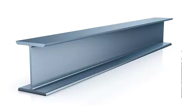
H-shaped steel—also known as I-beam steel (due to its cross-sectional resemblance to the letter “I” or “H”)—is a hot-rolled or welded structural steel profile defined by its unique cross-section: two parallel flanges (the horizontal top and bottom parts) connected by a central web (the vertical middle part). This design optimizes load-bearing capacity, making it a cornerstone of construction, infrastructure, and industrial projects worldwide. Unlike traditional angle steel or channel steel, H-shaped steel balances strength, rigidity, and material efficiency, enabling engineers to design safer, more cost-effective structures. Below is a detailed overview of its core characteristics, product variants, and unmatched advantages.
1. Core Product Overview of H-Shaped Steel
H-shaped steel is categorized based on manufacturing processes, dimensional standards, and material grades—each tailored to specific application needs.
Key Product Classifications
By Manufacturing Process
Hot-Rolled H-Shaped Steel: The most common type, produced by heating steel billets to 1,200–1,300°C and rolling them into the H-cross-section via precision mills. It features a continuous, homogeneous grain structure, delivering superior mechanical properties (e.g., tensile strength, impact resistance) and a smooth surface finish. Hot-rolled H-steel is ideal for heavy-load structures like bridges and high-rises.
Welded H-Shaped Steel: Fabricated by welding three steel plates (two flanges + one web) into the H-profile. This process allows for custom dimensions (e.g., extra-wide flanges or thick webs) that may be impractical for hot rolling. Welded H-steel is often used in specialized projects, such as industrial equipment frames or non-standard structural components.
By Dimensional Standards
Global standards define H-shaped steel sizes to ensure compatibility across projects. The most widely adopted standards include:
GB/T 11263 (China): Classifies H-steel into “wide-flange H-beams (HW),” “middle-flange H-beams (HM),” and “narrow-flange H-beams (HN)” based on flange width. For example:
HW series (wide flange): Flange width ≈ web height (e.g., HW200×200: 200mm web height, 200mm flange width) for heavy loads.
HN series (narrow flange): Flange width < web height (e.g., HN300×150: 300mm web height, 150mm flange width) for light-to-medium loads.
ASTM A6/A6M (USA): Covers “W-shapes” (wide-flange beams, equivalent to HW/HM) and “S-shapes” (standard I-beams, narrower flanges).
EN 10034 (EU): Defines “HE-profiles” (HEA, HEB, HEC), with HEB (wide flange) being the most similar to China’s HW series.
By Material Grade
H-shaped steel uses high-strength structural steel grades to meet diverse load and environmental demands:
Carbon steel grades: Q235B (China), A36 (USA), S235JR (EU) — suitable for general construction (e.g., residential buildings, light industrial frames) with minimum tensile strength of 375–460 MPa.
Low-alloy high-strength grades: Q355B (China), A572 Grade 50 (USA), S355JR (EU) — ideal for heavy-load or harsh-environment projects (e.g., bridges, offshore platforms) with tensile strength up to 510 MPa and better corrosion resistance.
2. Unmatched Advantages of H-Shaped Steel
H-shaped steel outperforms other structural profiles (e.g., angle steel, channel steel, square tubes) in key metrics that matter for construction efficiency, safety, and cost-effectiveness. Its advantages stem directly from its optimized cross-sectional design and high-quality material properties.
1.Exceptional Load-Bearing Capacity & Rigidity
The H-cross-section is engineered to distribute weight evenly, maximizing strength while minimizing material use:
High bending resistance: The wide flanges resist bending stress (the primary force in structural beams), while the thick web prevents shear deformation. For example, a Q355B HW300×300 H-beam can bear 2–3x more bending load than a channel steel of the same weight.
Uniform stress distribution: Unlike I-beams with narrower flanges, H-shaped steel’s balanced flange and web dimensions ensure stress is spread across the entire cross-section—reducing the risk of localized failure (e.g., flange buckling) under heavy loads.
High torsional rigidity: The closed H-profile resists twisting forces better than open profiles (e.g., angle steel), making it ideal for structures exposed to wind, seismic activity, or dynamic loads (e.g., factory cranes).
2.Superior Material Efficiency & Cost Savings
H-shaped steel’s design minimizes material waste while maintaining strength, translating to lower project costs:
High strength-to-weight ratio: It delivers more load capacity per unit weight than traditional profiles. For a 10-story office building, using H-shaped steel instead of channel steel can reduce the total steel weight by 15–20%—cutting material and transportation costs.
Reduced processing time: Hot-rolled H-steel requires minimal post-production processing (e.g., cutting, drilling) due to its precise dimensions. This speeds up on-site installation, shortening construction timelines by 10–15% compared to custom-welded profiles.
3. Easy Installation & Structural Versatility
H-shaped steel’s standardized dimensions and simple connection methods make it highly adaptable to diverse projects:
Simplified connections: It can be easily joined via welding, bolting, or riveting to other structural components (e.g., columns, braces). For example, in steel-framed buildings, H-beam beams are bolted to H-beam columns using flange plates—no complex custom fabrication required.
Flexible design compatibility: Available in a wide range of sizes (web height: 100mm–1,000mm; flange width: 100mm–500mm) to suit projects from small residential frames to large-span bridges. Welded H-steel further extends this versatility by allowing custom dimensions for unique needs (e.g., extra-tall webs for industrial mezzanines).
4. Excellent Durability & Environmental Adaptability
H-shaped steel maintains performance in harsh conditions, ensuring long-term structural safety:
Corrosion resistance (with treatments): Uncoated carbon steel H-beams work well in dry indoor environments (e.g., factory halls), while galvanized or epoxy-coated H-beams resist rust in outdoor or humid settings (e.g., coastal bridges, water treatment plants). Low-alloy grades (e.g., Q355ND) even offer weathering resistance for outdoor structures without additional coatings.
Temperature stability: It retains strength at both high and low temperatures. For example, Q355B H-steel maintains 80% of its tensile strength at -40°C (suitable for cold regions like northern China) and resists softening at temperatures up to 350°C (safe for industrial facilities with heat-generating equipment).
5. Eco-Friendliness & Recyclability
H-shaped steel aligns with sustainable construction trends:
High recyclability: Steel is 100% recyclable without losing quality. At the end of a structure’s lifespan, H-shaped steel can be melted down and reused to produce new steel products—reducing landfill waste and carbon emissions.
Low embodied carbon: Modern steel production (e.g., using electric arc furnaces with scrap steel) emits 70–80% less CO₂ than traditional blast furnace methods. Choosing H-shaped steel over concrete (a high-carbon material) can lower a project’s embodied carbon by 30–40%.
3. Why Choose H-Shaped Steel?
For engineers, contractors, and project owners, H-shaped steel is more than just a structural component—it is a strategic choice that balances safety, efficiency, and sustainability. Its ability to handle heavy loads, reduce costs, and adapt to diverse designs makes it the preferred profile for:
High-rise buildings (steel frames, floor beams)
Long-span structures (bridges, stadiums, airport terminals)
Industrial facilities (factory frames, crane beams, mezzanines)
Infrastructure projects (power transmission towers, highway guardrails)
Dimensional Tolerances for Hot-Rolled H-Beams
(Based on GB/T 11263-2010, ASTM A6/A6M-24, EN 10034:2017)
|
Dimension Category |
Symbol |
Standard & H-Beam Series |
Tolerance (mm) |
Measurement Specifications |
|
Section Height |
H |
GB/T 11263-2010 (HM/HN/HP Series) |
HM/HN (h100-h900): ±1.5mm (h≤200); ±2.0mm (200<h≤400); ±2.5mm (h>400) |
Measured vertically from the top of the upper flange to the bottom of the lower flange; exclude burrs |
|
|
|
ASTM A6/A6M-24 (W-Series) |
W4-W6: ±1.6mm; W8-W10: ±2.0mm; W12-W14: ±2.4mm; W16-W24: ±3.2mm |
Tolerance refers to the nominal depth marked in the grade (e.g., W10×49: nominal depth = 254mm) |
|
|
|
EN 10034:2017 (HEA/HEB/HEM Series) |
HEA (h100-h1000): ±1.2mm (h≤300); ±1.8mm (h>300) |
Based on the nominal section height (hₙₒₘ) of the HE series; measured at the center of flange width |
|
Flange Width |
B |
GB/T 11263-2010 (HM/HN/HP Series) |
HM/HN (b100-b400): ±1.0mm (b≤200); ±1.5mm (b>200) |
Measured horizontally across the full width of the flange; avoid measuring at edge burrs |
|
|
|
ASTM A6/A6M-24 (W-Series) |
W4-W6: ±1.0mm; W8-W10: ±1.3mm; W12-W14: ±1.6mm; W16-W24: ±2.0mm |
Tolerance relative to the nominal flange width in the grade (e.g., W10×49: nominal flange width = 152mm) |
|
|
|
EN 10034:2017 (HEA/HEB/HEM Series) |
HEA (b100-b400): ±0.8mm (b≤200); ±1.2mm (b>200) |
Measured at 1/4 and 3/4 of the flange length to ensure uniformity |
|
Web Thickness |
d |
GB/T 11263-2010 (All Series) |
±0.15×dₙₒₘ (minimum tolerance: 0.3mm; maximum tolerance: 1.5mm) |
Measured at 1/4 and 3/4 of the web height; avoid flange-web fillet regions (radius ≥5mm) |
|
|
|
ASTM A6/A6M-24 (W-Series) |
±15% of nominal web thickness (e.g., W10×49: dₙₒₘ=6.4mm → tolerance: ±0.96mm) |
Measurement points located 25mm from the flange-web junction (minimum distance to fillet) |
|
|
|
EN 10034:2017 (All Series) |
±10% of nominal web thickness (minimum tolerance: 0.2mm; maximum tolerance: 1.2mm) |
Tested with a digital caliper (accuracy: ±0.01mm) at 3 evenly spaced points on the web |
|
Flange Thickness |
t |
GB/T 11263-2010 (All Series) |
±0.15×tₙₒₘ (minimum tolerance: 0.3mm; maximum tolerance: 2.0mm) |
Measured at the mid-width of the flange; exclude edge thinning (≤0.5mm from edge) |
|
|
|
ASTM A6/A6M-24 (W-Series) |
±15% of nominal flange thickness (e.g., W10×49: tₙₒₘ=10.2mm → tolerance: ±1.53mm) |
Measurement taken 12.5mm from the flange edge (avoids edge burrs and thinning) |
|
|
|
EN 10034:2017 (All Series) |
±8% of nominal flange thickness (minimum tolerance: 0.2mm; maximum tolerance: 1.5mm) |
Measured at 1/3 and 2/3 of the flange width to check for thickness uniformity |
|
Web Offset (Eccentricity) |
- |
GB/T 11263-2010 (All Series) |
≤0.15×dₙₒₘ (maximum offset: 1.0mm for dₙₒₘ≤6mm) |
Difference between distances from web centerline to each flange’s inner edge |
|
|
|
ASTM A6/A6M-24 (W-Series) |
≤6% of nominal flange width (e.g., W10×49: Bₙₒₘ=152mm → max offset: 9.12mm) |
Eccentricity relative to flange width (not web thickness) to ensure load balance |
|
|
|
EN 10034:2017 (All Series) |
≤0.4mm (HEA/HEB h≤300); ≤0.6mm (HEA/HEB h>300); ≤0.8mm (HEM all sizes) |
Tested with a laser alignment tool for high-precision centering |
|
Length Tolerance |
L |
GB/T 11263-2010 (Fixed Length) |
+50/-0mm (L≤6m); +100/-0mm (6m<L≤12m); +150/-0mm (L>12m) |
Random length tolerance: +1000/-200mm (default); fixed length requires prior agreement |
|
|
|
ASTM A6/A6M-24 (Fixed Length) |
+25.4/-0mm (any fixed length) |
Random length range: 6.1m-18.3m (standard); custom lengths available via contract |
|
|
|
EN 10034:2017 (Fixed Length) |
+30/-0mm (L≤10m); +50/-0mm (L>10m) |
Random length tolerance: +1000/-200mm (unless specified otherwise in purchase order) |
Shape and Straightness Tolerances for Hot-Rolled H-Beams
|
Tolerance Type |
Standard Reference |
Tolerance Requirement |
Testing Method |
|
Axial Straightness |
GB/T 11263-2010 |
≤1.5mm/m (total straightness: ≤1.5×L mm, L=total length in meters; max 15mm for L>10m) |
Place a straightedge (length ≥1.5m) along the beam’s axis; measure gap with feeler gauge |
|
|
ASTM A6/A6M-24 |
≤1.6mm/m (max total deviation: 3.2mm for L≤6.1m; 6.4mm for 6.1m<L≤12.2m) |
Use a string line (tension ≥500N) to span the beam; measure maximum sag with dial gauge |
|
|
EN 10034:2017 |
≤1.0mm/m (total straightness: ≤1.0×L mm; max 10mm for L>10m) |
Laser straightness tester (accuracy: ±0.1mm/m) to scan the entire beam length |
|
Flange Flatness (Per 100mm) |
GB/T 11263-2010 |
≤0.5mm/100mm (max deviation across full flange width: ≤2.0mm for B≤400mm) |
Place a precision straightedge (grade 1) on the flange; measure gap at 3 points |
|
|
ASTM A6/A6M-24 |
≤0.8mm/100mm (flange edge camber ≤1.0mm/m; no sharp bends >1.5mm) |
Straightedge spans the full flange width; use digital feeler gauge (±0.001mm) |
|
|
EN 10034:2017 |
≤0.3mm/100mm (max deviation across full flange width: ≤1.5mm for B≤400mm) |
Optical flat (λ/4 accuracy) used to check flatness via interference fringes |
|
Web Verticality |
GB/T 11263-2010 |
90°±1° (angle between flange and web; measured at 3 points: top, middle, bottom) |
Digital protractor (±0.1° accuracy) placed at flange-web fillet; average 3 readings |
|
|
ASTM A6/A6M-24 |
90°±1.5° (light grades: W4-W10); 90°±2° (heavy grades: W12-W24) |
Protractor with magnetic base; measure at both ends of the beam |
|
|
EN 10034:2017 |
90°±0.5° (HEB/HEM series); 90°±0.8° (HEA series) |
Coordinate measuring machine (CMM) to map flange-web angle in 3D space |
|
Flange Parallelism |
GB/T 11263-2010 |
≤1.0mm/m (max difference between flange heights: ≤2.0mm for L≤6m) |
Measure distance between flanges at 4 corners of the beam; calculate difference |
|
|
ASTM A6/A6M-24 |
≤1.2mm/m (max difference: ≤3.0mm for L≤12.2m) |
Use a depth gauge (±0.01mm) to test flange height at 6 evenly spaced points |
|
|
EN 10034:2017 |
≤0.8mm/m (max difference: ≤1.5mm for L≤10m) |
Laser distance sensor to scan flange surfaces and compare parallelism |
Notes:
All tolerances apply to hot-rolled H-beams in the as-delivered state (no post-processing). For machined or welded H-beams, custom tolerance agreements with manufacturers are required.
Burrs on flange edges or web ends are allowed up to 0.5mm (GB/T 11263) or 1.0mm (ASTM/EN) in height and do not count toward dimensional deviations.
High-strength H-beams (e.g., Q460 in GB/T 11263, A992 in ASTM A6) may have slightly relaxed web/flange thickness tolerances (±18% instead of ±15%)—refer to standard supplements for details.
Tolerance verification must be conducted at room temperature (20℃±5℃) to avoid thermal expansion/contraction errors in measurements.
Chemical Composition of H-Beams (Mass Fraction, ≤ %)
|
Standard & Grade |
C (Carbon) |
Si (Silicon) |
Mn (Manganese) |
P (Phosphorus) |
S (Sulfur) |
Cr (Chromium) |
Ni (Nickel) |
Mo (Molybdenum) |
V (Vanadium) |
|
GB/T 11263-2010 |
|
|
|
|
|
|
|
|
|
|
- Q235B |
0.12-0.20 |
≤ 0.30 |
0.30-0.70 |
≤ 0.045 |
≤ 0.045 |
≤ 0.30 |
≤ 0.30 |
- |
- |
|
- Q355B |
≤ 0.18 |
≤ 0.55 |
1.00-1.60 |
≤ 0.035 |
≤ 0.035 |
≤ 0.30 |
≤ 0.30 |
≤ 0.10 |
≤ 0.05 |
|
- Q460C |
≤ 0.20 |
≤ 0.60 |
1.00-1.80 |
≤ 0.030 |
≤ 0.030 |
≤ 0.70 |
≤ 0.50 |
≤ 0.20 |
≤ 0.15 |
|
ASTM A6/A6M-24 |
|
|
|
|
|
|
|
|
|
|
- A36 |
≤ 0.25 |
≤ 0.40 |
0.85-1.20 |
≤ 0.040 |
≤ 0.050 |
- |
- |
- |
- |
|
- A992 (HSLA) |
≤ 0.23 |
≤ 0.35 |
1.00-1.50 |
≤ 0.035 |
≤ 0.035 |
≤ 0.30 |
≤ 0.50 |
≤ 0.10 |
≤ 0.08 |
|
EN 10025-2:2019 |
|
|
|
|
|
|
|
|
|
|
- S235JR |
≤ 0.17 |
≤ 0.35 |
≤ 1.40 |
≤ 0.045 |
≤ 0.045 |
≤ 0.30 |
≤ 0.30 |
- |
- |
|
- S355JR |
≤ 0.20 |
≤ 0.55 |
≤ 1.60 |
≤ 0.035 |
≤ 0.035 |
≤ 0.30 |
≤ 0.30 |
≤ 0.10 |
≤ 0.05 |
|
- S460N |
≤ 0.20 |
≤ 0.60 |
≤ 1.70 |
≤ 0.025 |
≤ 0.025 |
≤ 0.70 |
≤ 0.80 |
≤ 0.30 |
≤ 0.15 |
Mechanical Properties of H-Beams
|
Standard & Grade |
Yield Strength (Rp0.2, ≥ MPa) |
Tensile Strength (Rm, MPa) |
Elongation After Fracture (A, ≥ %) |
Impact Absorption Energy (KV2, ≥ J) |
Delivery State |
Typical Applications |
|
GB/T 11263-2010 |
|
|
|
|
|
|
|
- Q235B |
235 |
375-500 |
26 |
≥ 27 (20℃) |
Hot-rolled |
Building frames, light industrial structures |
|
- Q355B |
355 |
470-630 |
22 |
≥ 34 (20℃) |
Hot-rolled |
Heavy machinery, bridge girders, high-rise columns |
|
- Q460C |
460 |
550-720 |
19 |
≥ 34 (-40℃) |
Normalized |
Large-span bridges, offshore platforms |
|
ASTM A6/A6M-24 |
|
|
|
|
|
|
|
- A36 |
250 |
400-550 |
20 |
≥ 27 (Room temp) |
Hot-rolled |
Warehouses, commercial buildings, general construction |
|
- A992 (HSLA) |
345 |
450-620 |
18 |
≥ 34 (-10℃) |
Hot-rolled |
Highway bridges, heavy-duty frames |
|
EN 10025-2:2019 |
|
|
|
|
|
|
|
- S235JR |
235 |
360-510 |
26 |
≥ 27 (20℃) |
Hot-rolled |
Civil engineering, low-rise buildings |
|
- S355JR |
355 |
470-630 |
22 |
≥ 34 (20℃) |
Hot-rolled |
Industrial plants, crane structures |
|
- S460N |
460 |
550-700 |
19 |
≥ 34 (-40℃) |
Normalized |
Wind turbine towers, mining equipment |
Notes:
All values conform to the latest versions of the referenced standards (as of 2024). For specialized grades or custom requirements, consult official standards or manufacturers.
Impact energy values are tested at the temperature specified (e.g., 20℃ for Q235B, -40℃ for S460N). For cold-climate applications, select grades with low-temperature suffixes (e.g., Q355D, S355JO).
Mechanical properties reflect the as-delivered state (hot-rolled or normalized). Heat treatment (e.g., quenching) will alter performance and requires additional testing.
H-beams for corrosive environments (e.g., marine use) require supplementary anti-corrosion treatments (e.g., galvanizing). This table does not include corrosion resistance data.


Katherine A. Fogg
Your email address will not be published. Required fields are marked with *
Their products are of excellent quality and they offer generous discounts. This is their third cooperation