
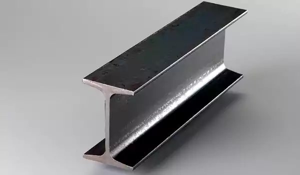
I-beam
Steel Beams are widely used throughout the construction industry when supporting heavy loads is required. Commonly termed an “I” Beam because of its shape, beams provide great load bearing support when used horizontally or standing as columns. Available in two configurations, the most popular being the Wide Flange Steel Beam aka H Beam or W Beam with non-tapered flanges. This beam shape has a wider profile for added horizontal strength, making it ideal for skyscrapers or as a house beam, along with bridge beams, trailers, platforms, etc. Standard American Beams, aka Junior Beams or S Beams, have tapered flanges for added strength when your load is concentrated on the flanges, such as machine bases, hoists, cranes or a trolley beam for your garage.
Dimensional Tolerances for Hot-Rolled I-Beams (Based on GB/T 706-2016, ASTM A6/A6M-24, EN 10034:2017)
|
Dimension Category |
Symbol |
Standard & Grade Range |
Tolerance (mm) |
Measurement Notes |
|
Section Height |
H |
GB/T 706-2016 (h100-h1000) |
h100-h200: ±1.5; h220-h400: ±2.0; h450-h600: ±2.5; h630-h1000: ±3.0 |
Measured from the top of the upper flange to the bottom of the lower flange |
|
|
|
ASTM A6/A6M-24 (W4×13 to W14×340) |
W4-W6: ±1.6; W8-W10: ±2.0; W12-W14: ±2.4 |
Tolerance applies to the nominal depth specified in the grade designation |
|
|
|
EN 10034:2017 (IPE80-IPE600) |
IPE80-IPE140: ±1.0; IPE160-IPE240: ±1.2; IPE270-IPE400: ±1.5; IPE450-IPE600: ±2.0 |
Based on the nominal height (h<sub>nom</sub>) of the IPE series |
|
Flange Width |
B |
GB/T 706-2016 (h100-h1000) |
h100-h200: ±1.0; h220-h400: ±1.5; h450-h600: ±2.0; h630-h1000: ±2.5 |
Measured across the full width of the flange (excluding burrs) |
|
|
|
ASTM A6/A6M-24 (W4×13 to W14×340) |
W4-W6: ±1.0; W8-W10: ±1.3; W12-W14: ±1.6 |
Tolerance is relative to the nominal flange width in the grade |
|
|
|
EN 10034:2017 (IPE80-IPE600) |
IPE80-IPE140: ±0.8; IPE160-IPE240: ±1.0; IPE270-IPE400: ±1.2; IPE450-IPE600: ±1.5 |
Applies to the nominal flange width (b<sub>nom</sub>) of the IPE series |
|
Web Thickness |
d |
GB/T 706-2016 (h100-h1000) |
±0.15d (d = nominal web thickness) |
Measured at the mid-height of the web, avoiding flange-web fillet areas |
|
|
|
ASTM A6/A6M-24 (W4×13 to W14×340) |
±15% of nominal web thickness |
Measurement taken 25 mm from the flange-web junction (minimum distance) |
|
|
|
EN 10034:2017 (IPE80-IPE600) |
±10% of nominal web thickness (minimum tolerance: 0.3 mm) |
Test points located at 1/4 and 3/4 of the web height |
|
Flange Thickness |
t |
GB/T 706-2016 (h100-h1000) |
±0.15t (t = nominal flange thickness) |
Measured at the mid-width of the flange, excluding edge burrs |
|
|
|
ASTM A6/A6M-24 (W4×13 to W14×340) |
±15% of nominal flange thickness |
Measurement taken 12.5 mm from the flange edge (minimum distance) |
|
|
|
EN 10034:2017 (IPE80-IPE600) |
±10% of nominal flange thickness (minimum tolerance: 0.3 mm) |
Test points located at 1/4 and 3/4 of the flange width |
|
Web Offset (Web Eccentricity) |
- |
GB/T 706-2016 (all grades) |
≤ 0.15d |
Difference between distances from web centerline to each flange edge |
|
|
|
ASTM A6/A6M-24 (all grades) |
≤ 6% of nominal flange width |
Eccentricity relative to the flange width (not web thickness) |
|
|
|
EN 10034:2017 (all grades) |
≤ 0.5 mm (IPE80-IPE240); ≤ 0.8 mm (IPE270-IPE600) |
Tolerance for web misalignment relative to the flange centerline |
|
Length Tolerance (Delivery Length) |
L |
GB/T 706-2016 (fixed length) |
+50 / -0 mm (length ≤ 6m); +100 / -0 mm (length > 6m) |
Applies to fixed-length delivery (random length: +1000 / -200 mm) |
|
|
|
ASTM A6/A6M-24 (fixed length) |
+25.4 / -0 mm (any fixed length) |
Random length range: 6.1m - 18.3m (standard); special lengths by agreement |
|
|
|
EN 10034:2017 (fixed length) |
+30 / -0 mm (length ≤ 10m); +50 / -0 mm (length > 10m) |
Random length tolerance: +1000 / -200 mm (unless specified otherwise) |
Shape and Straightness Tolerances for Hot-Rolled I-Beams
|
Tolerance Type |
Standard Reference |
Tolerance Requirement |
Testing Method |
|
Section Straightness (Per Meter) |
GB/T 706-2016 |
≤ 1.5 mm/m (total straightness: ≤ 1.5×L mm, L = total length in meters) |
Measured by placing a straightedge along the beam’s axis; gap checked with feeler gauge |
|
|
ASTM A6/A6M-24 |
≤ 1.6 mm/m (maximum total deviation: 3.2 mm for lengths ≤ 6.1m; proportional for longer) |
Same as above; tolerance applies to both axial and lateral straightness |
|
|
EN 10034:2017 |
≤ 1.0 mm/m (total straightness: ≤ 1.0×L mm, L = total length in meters) |
Straightedge placed on flange or web surface; gap measured at maximum deviation point |
|
Flange Flatness (Per 100mm Width) |
GB/T 706-2016 |
≤ 0.5 mm/100mm (maximum deviation across full flange width) |
Feeler gauge used to measure gap between flange surface and straightedge |
|
|
ASTM A6/A6M-24 |
≤ 0.8 mm/100mm (flange edge may have slight camber, but no sharp bends) |
Straightedge spans full flange width; deviation measured at mid-width and edges |
|
|
EN 10034:2017 |
≤ 0.3 mm/100mm (strict flatness for precision applications like machinery frames) |
Tested with a precision straightedge (grade 1) and digital feeler gauge |
|
Web Verticality (Flange-Web Angle) |
GB/T 706-2016 |
90° ± 1° (angle between flange and web) |
Protractor used at flange-web fillet (3 points per section: top, middle, bottom) |
|
|
ASTM A6/A6M-24 |
90° ± 1.5° (allowable deviation for heavy-duty grades; ±1° for light grades) |
Angle measured at both ends of the beam; average deviation must meet tolerance |
|
|
EN 10034:2017 |
90° ± 0.5° (high precision for structural integrity in load-bearing applications) |
Digital protractor (accuracy: ±0.1°) used at 4 points per section |
Notes:
All tolerances above are for hot-rolled I-beams in the as-delivered state (no additional heat treatment or machining). Machined I-beams require custom tolerance agreements with manufacturers.
For special grades (e.g., high-strength low-alloy (HSLA) I-beams like Q460 in GB/T 706 or A992 in ASTM A6), check the specific standard supplement for modified tolerances (usually slightly looser for web thickness).
Burrs on flange edges or web ends are allowed up to 0.5 mm in height (GB/T 706) or 1.0 mm (ASTM/EN) and do not count towards dimensional tolerance deviations.
Tolerance verification should be conducted at room temperature (20℃ ± 5℃) to avoid thermal expansion/contraction effects on measurement accuracy.
Chemical Composition of I-Beams (Mass Fraction, ≤ %)
|
Standard & Grade |
C (Carbon) |
Si (Silicon) |
Mn (Manganese) |
P (Phosphorus) |
S (Sulfur) |
Cr (Chromium) |
Ni (Nickel) |
Cu (Copper) |
|
GB/T 706-2016 |
|
|
|
|
|
|
|
|
|
- Q235B |
0.12-0.20 |
≤ 0.30 |
0.30-0.70 |
≤ 0.045 |
≤ 0.045 |
≤ 0.30 |
≤ 0.30 |
≤ 0.30 |
|
- Q355B |
≤ 0.18 |
≤ 0.55 |
1.00-1.60 |
≤ 0.035 |
≤ 0.035 |
≤ 0.30 |
≤ 0.30 |
≤ 0.30 |
|
- Q460C |
≤ 0.20 |
≤ 0.60 |
1.00-1.80 |
≤ 0.030 |
≤ 0.030 |
≤ 0.70 |
≤ 0.50 |
≤ 0.30 |
|
ASTM A6/A6M-24 |
|
|
|
|
|
|
|
|
|
- A36 |
≤ 0.25 |
≤ 0.40 |
0.85-1.20 |
≤ 0.040 |
≤ 0.050 |
- |
- |
- |
|
- A992 (HSLA) |
≤ 0.23 |
≤ 0.35 |
1.00-1.50 |
≤ 0.035 |
≤ 0.035 |
≤ 0.30 |
≤ 0.50 |
≤ 0.30 |
|
EN 10025-2:2019 |
|
|
|
|
|
|
|
|
|
- S235JR |
≤ 0.17 |
≤ 0.35 |
≤ 1.40 |
≤ 0.045 |
≤ 0.045 |
≤ 0.30 |
≤ 0.30 |
≤ 0.30 |
|
- S355JR |
≤ 0.20 |
≤ 0.55 |
≤ 1.60 |
≤ 0.035 |
≤ 0.035 |
≤ 0.30 |
≤ 0.30 |
≤ 0.30 |
|
- S460N |
≤ 0.20 |
≤ 0.60 |
≤ 1.70 |
≤ 0.025 |
≤ 0.025 |
≤ 0.70 |
≤ 0.80 |
≤ 0.30 |
Mechanical Properties of I-Beams
|
Standard & Grade |
Yield Strength (Rp0.2, ≥ MPa) |
Tensile Strength (Rm, MPa) |
Elongation After Fracture (A, ≥ %) |
Impact Absorption Energy (KV2, ≥ J) |
Delivery State |
Typical Applications |
|
GB/T 706-2016 |
|
|
|
|
|
|
|
- Q235B |
235 |
375-500 |
26 |
≥ 27 (20℃) |
Hot-rolled |
Building frames, light machinery brackets |
|
- Q355B |
355 |
470-630 |
22 |
≥ 34 (20℃) |
Hot-rolled |
Heavy-duty steel structures, engineering machinery |
|
- Q460C |
460 |
550-720 |
19 |
≥ 34 (-40℃) |
Normalized |
High-rise building columns, bridge load-bearing parts |
|
ASTM A6/A6M-24 |
|
|
|
|
|
|
|
- A36 |
250 |
400-550 |
20 |
≥ 27 (Room temp) |
Hot-rolled |
Bridges, warehouses, pressure vessels (non-critical) |
|
- A992 (HSLA) |
345 |
450-620 |
18 |
≥ 34 (-10℃) |
Hot-rolled |
Highway bridges, large-span steel structures |
|
EN 10025-2:2019 |
|
|
|
|
|
|
|
- S235JR |
235 |
360-510 |
26 |
≥ 27 (20℃) |
Hot-rolled |
Industrial plants, civil buildings |
|
- S355JR |
355 |
470-630 |
22 |
≥ 34 (20℃) |
Hot-rolled |
Offshore structures, crane booms |
|
- S460N |
460 |
550-700 |
19 |
≥ 34 (-40℃) |
Normalized |
Wind turbine towers, heavy engineering |
Notes:
All data complies with the latest versions of the corresponding standards (as of May 2024). For custom grades or special requirements (e.g., low-temperature toughness), consult the official standard documents or steel manufacturers.
Impact absorption energy is tested under the temperature specified in the grade (e.g., 20℃ for Q235B, -40℃ for Q460C). For colder environments, select grades with suffixes like “D” or “E” (e.g., Q355D, S355JO).
Mechanical properties are based on the hot-rolled or normalized delivery state. Heat treatment (e.g., quenching and tempering) will alter performance, requiring additional testing for verification.
For I-beams used in corrosive environments (e.g., marine, chemical plants), additional anti-corrosion treatment (e.g., galvanizing, painting) is recommended—this table does not include corrosion resistance indicators.


Katherine A. Fogg
Your email address will not be published. Required fields are marked with *
Their products are of excellent quality and they offer generous discounts. This is their third cooperation